An MCC (Motor Control Center) bucket is a modular, enclosed compartment within an MCC panel that contains all the control and protection components required to operate a motor or group of motors. These buckets are designed to control motors of various sizes and configurations, and they are commonly used in industrial and commercial environments for controlling motors in processes such as HVAC, water treatment, manufacturing, and pumping systems. Each bucket can be inserted or removed from the MCC structure, making it easy to service or replace components without disturbing the entire system. Here are the key components of an MCC bucket:
Key Components of an MCC Bucket
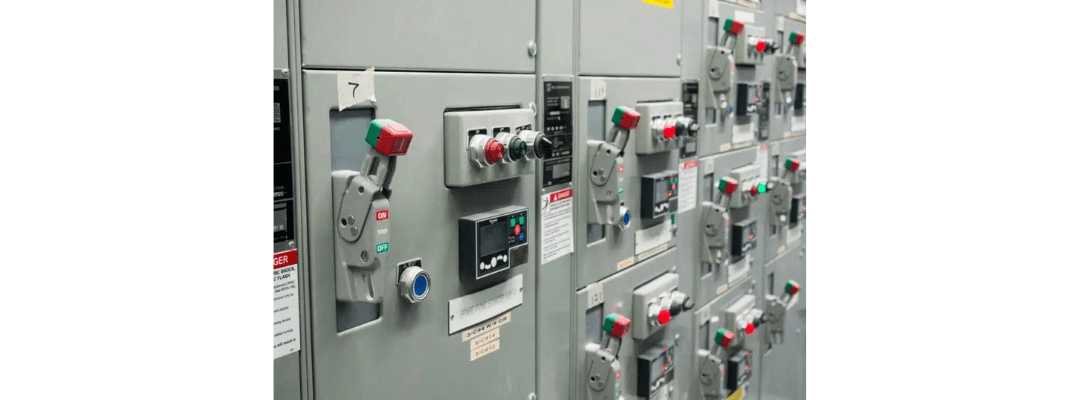
1. Circuit Breaker or Fusible Disconnect Switch
Function: The circuit breaker or fusible disconnect switch provides overcurrent and short-circuit protection for the motor and its control components. It serves as the main disconnect for isolating the motor circuit and is the first point of control in the bucket.
Types:
- Circuit Breaker: Provides resettable overcurrent protection and can be operated manually or automatically in the event of a fault.
- Fusible Disconnect Switch: Uses fuses to protect against overcurrent. It requires fuse replacement if a fault occurs.
- Control: Often features an external handle for manually disconnecting the power to the motor and providing visible isolation for safety during maintenance.
2. Contactor
- Function: A contactor is an electromechanical switch that is used to start and stop the motor by controlling the flow of electrical power. When the control system sends a signal, the contactor engages or disengages the motor by making or breaking the connection to the power supply.
- Operation: It is energized by a control signal (often from a PLC or a push button), which allows current to flow to the motor.
- Contact Rating: The contactor must be rated according to the motor’s voltage and current requirements.
3. Overload Relay
Function: The overload relay provides protection against sustained overcurrent conditions that could damage the motor due to overheating. It does not protect against short circuits but reacts to prolonged overloading conditions.
Types:
- Thermal Overload Relay: Uses bimetallic strips that bend when heated by excessive current, triggering the relay to disconnect the motor.
- Electronic Overload Relay: Uses electronic sensors to monitor the current and provides more precise and adjustable protection.
Reset: Many overload relays have a manual or automatic reset feature that restores motor operation after an overload condition has been cleared.
4. Control Transformer
- Function: The control transformer provides stepped-down voltage from the main power supply to the control circuit. In many cases, the control devices (like contactors and relays) require a lower voltage (typically 120V AC or 24V DC) than the motor, so the transformer is necessary to supply power to the control side of the MCC bucket.
- Secondary Voltage: Typically provides low-voltage AC or DC power for control components such as push buttons, pilot lights, or control relays.
5. Push Buttons and Selector Switches
Function: Push buttons and selector switches provide manual control over motor operation. They allow operators to start, stop, or change modes of the motor (such as from manual to automatic).
Common Types:
- Start/Stop Buttons: Simple push buttons that control motor start and stop functions.
- Selector Switches: Allow switching between modes such as “Manual/Auto” or “Forward/Reverse.”
Location: These components are often mounted on the front of the MCC bucket for easy access by operators.
6. Pilot Lights
- Function: Pilot lights provide a visual indication of the operating status of the motor or system. They can indicate states such as “Motor Running,” “Stopped,” “Tripped,” or “Fault Condition.”
- Color Codes: Different colors indicate different statuses:
- Green: Motor running
- Red: Motor stopped
- Amber: Fault or warning condition
7. Control Relay
- Function: Control relays are electromechanical switches used to control various aspects of motor operation, such as sequencing or interlocking. They allow for complex control logic by switching the state of one circuit based on signals from another circuit.
- Application: Control relays are often used for control logic functions like motor interlocking, timed delays, or feedback from external sensors.
8. Current Transformers (CTs)
- Function: Current transformers are used to monitor the current going to the motor and provide feedback for control or metering purposes. They step down high current to a lower, measurable level, which is then used for protection, measurement, or control functions.
- Application: CTs are typically used for protection (e.g., overload or fault detection) and for providing current measurement for system monitoring.
9. Fuses
- Function: Fuses provide additional overcurrent protection by blowing when excessive current flows through the circuit. They are typically used to protect individual components like control transformers or auxiliary circuits within the bucket.
- Location: Fuses are mounted within the MCC bucket for easy replacement in case of a fault.
10. Terminal Blocks
- Function: Terminal blocks provide connection points for external wiring to the MCC bucket. They organize the wiring for control signals, power, and communication lines entering and leaving the bucket.
- Application: Used for simplifying wiring and for connecting field devices (sensors, actuators) to the control circuits in the MCC bucket.
11. VFD (Variable Frequency Drive) – Optional
- Function: A Variable Frequency Drive (VFD) is an optional component that allows for variable speed control of motors. It adjusts the frequency and voltage supplied to the motor, enabling precise control over motor speed and torque.
- Advantages: VFDs improve energy efficiency, reduce mechanical stress during start-up, and allow for more precise process control.
- Mounting: If included, the VFD is usually housed within the MCC bucket or adjacent to it, and is controlled by the PLC or control logic within the Motor Control Centre panel.
12. Soft Starter – Optional
- Function: A soft starter gradually increases the voltage to the motor during start-up, reducing inrush current and mechanical stress on the motor. This smooth start prevents wear and tear on mechanical components and reduces the risk of electrical faults.
- Application: Typically used in applications where motors experience heavy loads during start-up or where minimizing mechanical stress is important.
13. Metering and Monitoring Devices
- Function: These devices measure key performance indicators such as current, voltage, power, and power factor. They allow operators to monitor motor performance and energy consumption, helping to ensure efficiency and prevent failures.
- Digital or Analog: Meters can be digital (displayed on a screen) or analogue, providing visual feedback to operators.
14. PLC (Programmable Logic Controller) or DCS Integration – Optional
- Function: Some MCC buckets include a PLC or are integrated with a Distributed Control System (DCS) to automate motor control. The PLC handles complex control logic, timing sequences, and feedback signals for the entire system.
- Automation: With PLC integration, motor control can be automated and tied into a larger plant-wide control system.
Features of an MCC Bucket
- Modularity: MCC buckets are designed to be modular, meaning individual buckets can be added, removed, or replaced without disrupting the entire system. This makes maintenance and upgrades easier and more efficient.
- Safety Interlocks: MCC buckets often include safety interlocks to prevent accidental operation during maintenance. For example, the bucket cannot be removed while the power is still on.
- Front-Accessible Components: Key components, such as circuit breakers, push buttons, and pilot lights, are mounted on the front of the MCC bucket for easy access during operation and maintenance.
Recent Comments